Overengineered Automatic Cat Feeder
The Monsters
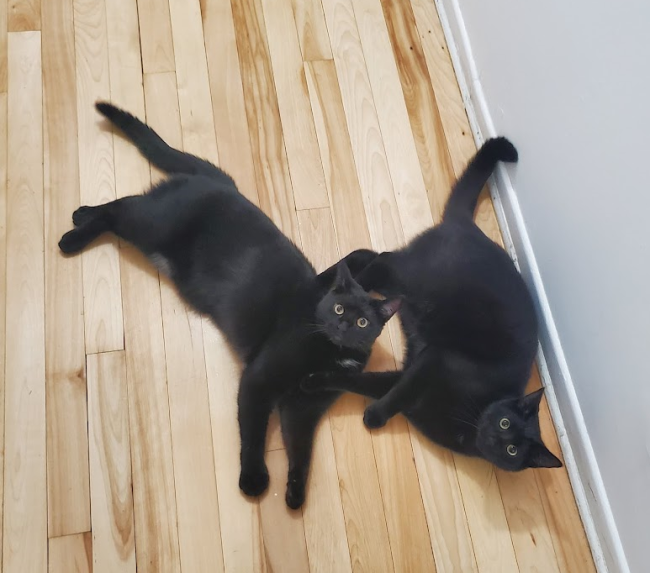
Two little perfect black balls of hair have elected domicile in my home. They are lovely, cuddly and HUNGRY!
When 6h AM rings, they come screaming and scratching at the door. Because I value my sleep and because I love adding to my pile of unfinished projects, I decided to make them an automatic cat feeder. Little did I know it would take me years to complete it.
The Idea
I had a few requirements, I wanted the machine to be:
-
reliable
The most important thing is that it works, and that it works consistently. -
safe
If it doesn't work, I should be alerted one way or another.
Can't let the poor kittens starve because something malfunctioned. -
configurable
If I need to change at which hour they get fed or how much to feed them, I don't want to be required to reprogram the device, there should be some sort of interface. -
perennial
Ideally the reservoir should be big enough so that I can put at least a month worth of food. I want to just fill it and forget about it.
At the time we had a little litter box furniture, with an empty spot of the same size next to it. I thought it would be perfect to make my machine of the same size. I had been looking for an excuse to use an ESP32 with a camera for a while, this was the perfect opportunity. So the plan at that point was:
- A big wood box for the structure and the reservoir
- An ESP32 with a cam module, so I can spy on the little creatures
- A webserver running on the ESP for the configuration interface and view the video feed
- An Arduino Nano for handling controlling the electronics
- Some sort of mechanism that can measure and dispense the food
- Some sensor to detect of the food was actually dispensed
The reason I decided to use an Arduino in addition to the ESP is that the location I wanted to put the camera in was a bit far from where the rest of the electronics would be. Also, the ESP32-CAM board I had had a limited number of GPIO available and they can only provide 3.3V. Most of the parts I already had required 5V.
The Structure
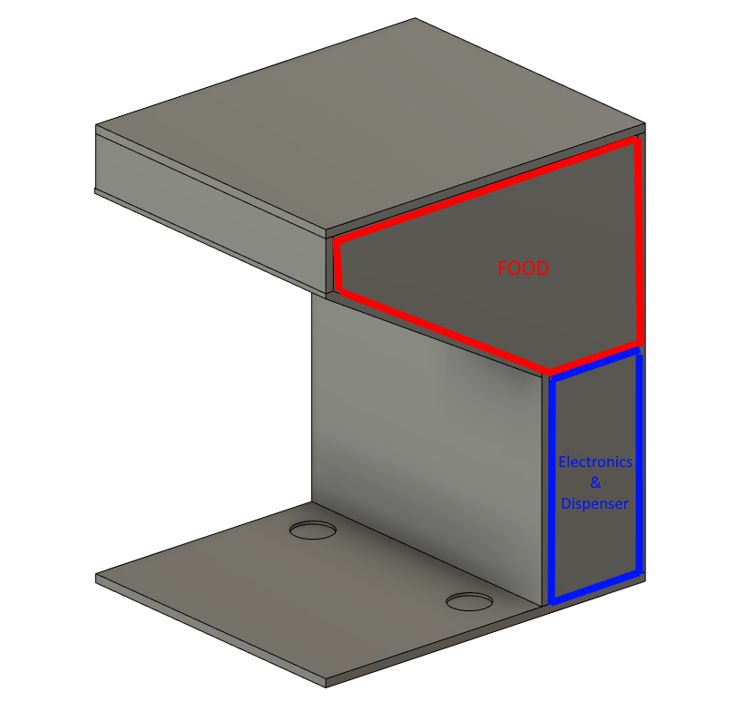
One of the first thing I designed is the box. I took the dimension of the litter box furniture then guesstimated the width and height that would be needed for the electronics and dispenser parts. Leading to that compartment I added a 30 degree slope and that was basically it.
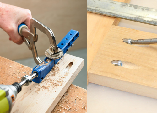
Once I had all the dimension it was a matter of laying out all the different rectangles together to see which size of plywood I needed to buy. I cut up the plywood with a circular saw and joined them with pocket holes. It was my first time trying pocket holes and I have to say, they are AWESOME.
It's basically a guide you clamp on the edge of a board, you adjust it for the width of your wood and when you drill with the special bit it makes a hole of the perfect angle and depth to screw into an adjacent board. It's super easy and quick to use and I couldn't be happier with the result, the box is super sturdy and rigid!
The structure's finishing touches were a coat of primer and white cabinet paint. I also added hinge for the top lid as well as a chest latch, to prevent the little devils from opening the lid and eating all the food.
The front access panel was originally on a hinge too but I later switched it to being screwed, it was easier to get right and it makes the inside much more accessible, which is nice for an access panel.
The First Prototype
During a failed attempt at making an automatic kombucha machine (automate all the things!) I designed an auger in OpenSCAD. OpenSCAD is a script-based CAD program and it's super fun, I'll probably make a blog post on that subject at some point. Anyways, the auger was fully parametric and powered by a 28byj-48 stepper motor. It seemed like a perfect fit for this project!
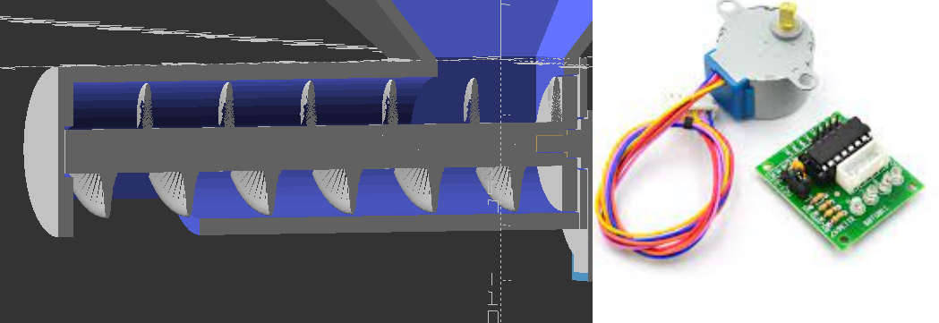
The issue is that that stepper motor isn't particularly strong. I found both the speed and the torque to be pretty low, even when overpowering it a bit. It took quite a while but after many iterations I figured out the right parameter of size, taper and angle for the auger to dispense food without getting stuck all the time. It was still very slow and tended to get stuck, but I was stuck too and it was time to move on to the next part.
My idea was to use a weight sensor to measure how much food to dispense. I designed a box with two compartment and the bottom of it swivels on an axis, a string was attached to the plate and connected to a wheel on a servo motor, turning the wheel pulls on the string, closing the bottom. The wire was routed over a weight sensor, so that the weight of the food on the plate would be applied on the sensor and it could be used to measure the amount of food in the compartments. In addition there's a "selector" tunnel, also on a servo motor, to control which compartment the food goes in, allowing the machine to dispense an equal amount of food into two bowls.
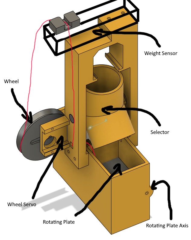
Most of it was working fine, the servo was able to rotate the wheel to open and close the bottom, the other servo rotated the selector to channel the food to one chamber or the other. The weight sensor mostly worked, the issue is that I was getting very inconsistent issue, the same amount of food would give me a different weight. I think the issue was due to the string not sliding perfectly in the channel and the friction between the food and the wall of the chambers. The weight sensor worked correctly outside of the machine so it was down to mechanical issues.
I tried different strings but I couldn't manage to get good results. Then I realized that design was quite tall and wouldn't fit very well inside the structure. It was time for a new prototype!
The Second Prototype
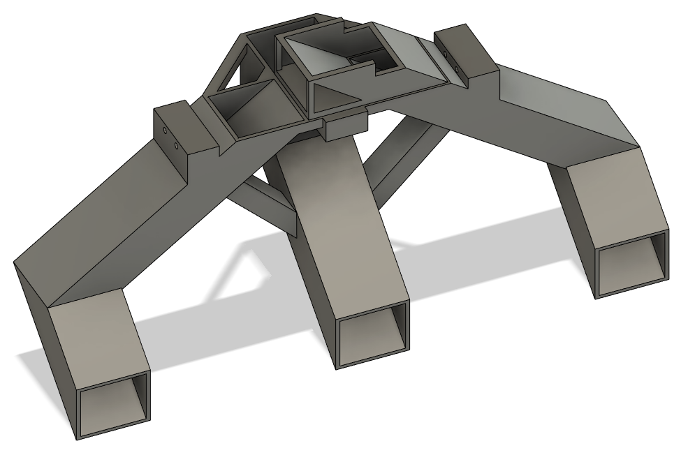
After reviewing how others have achieved this task, and trying to inspire myself from what I've learned in solving the auger's constant jamming issues, I went for a design with a wheel on a vertical axis, with long paddles that divide the body into chambers, an access to fill those chamber from the top on one side and a hole to dispense from the bottom on the opposite side.
And it worked very well! No jamming no nothin'! It helped that I used one of those classic 5V DC motor with a little gearbox, like those you can find in toys, they have much more torque than the stepper I tried to use previously.
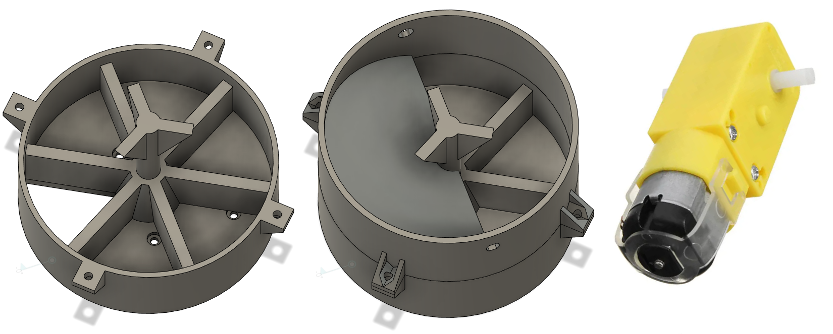
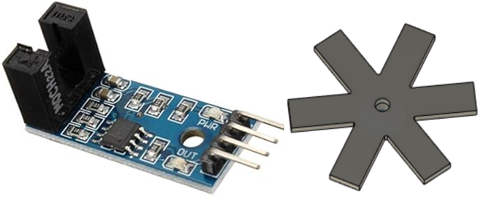
To keep track of the position of the wheel I used an infrared optical encoder, it simply gives you a signal depending on if something is between two black leg or not. I printed an encoder wheel that attached to the motor and voila! At the beginning I had issues with the inconsistent signals from the encoder, I tried to make the "teeth" of the wheel wider and wider until I realized it was simply too transparent, after giving it a couple coats of black sharpie it worked perfectly.
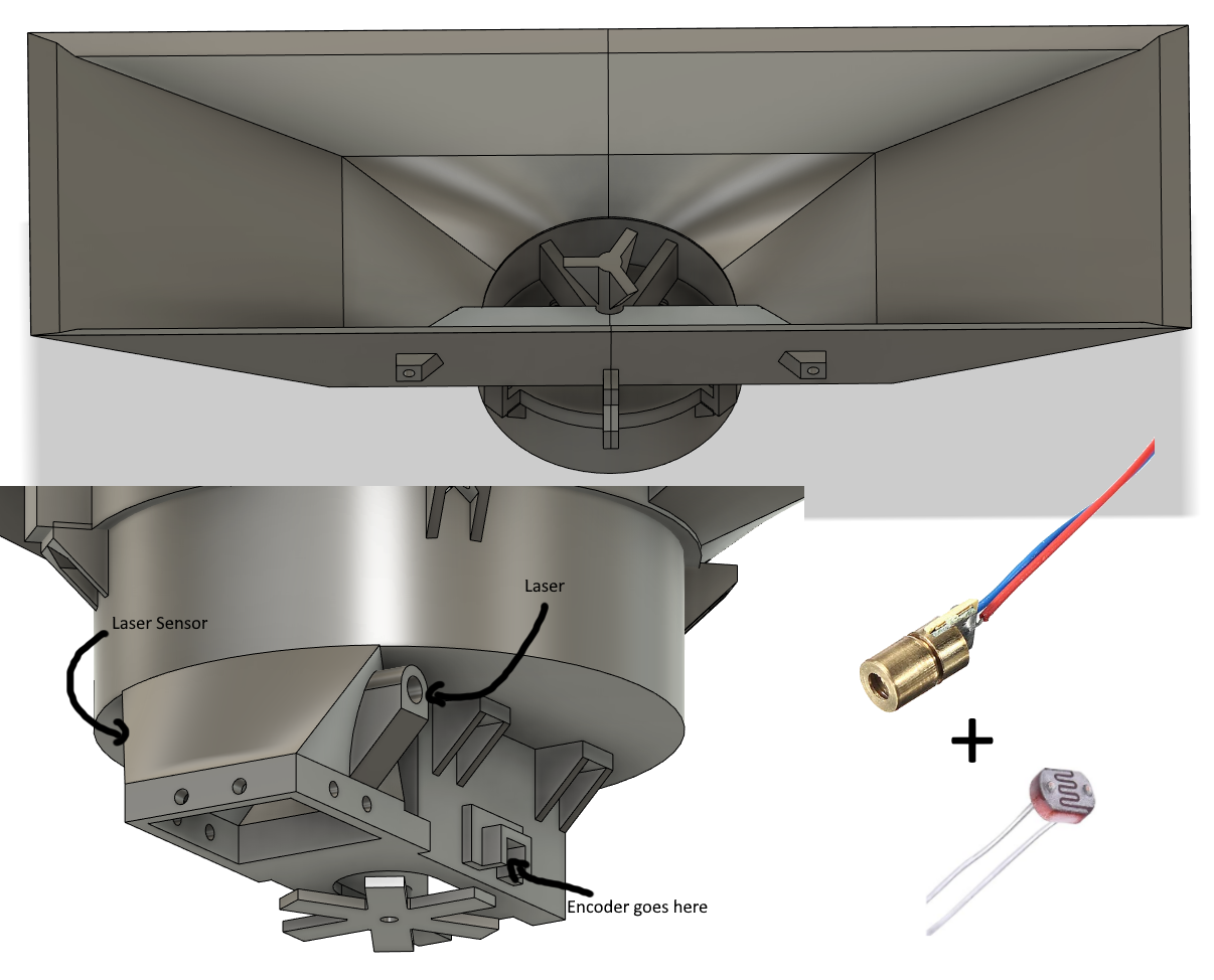
To save space I replaced the previous top part with a big funnel, printed in two part so it can fit on my printer. I printed a second part that goes on the bottom that holds the motor and the encoder, it also has two holes, one for a 5v laser and one for a photoresitor. The idea is that when the food falls through the chute it'll break the laser line and the microcontroller can monitor the photoreistor's value to detect if food was actually dispensed or not.
The first tunnel I designed were absolutely terrible, round angled shapes are not easy to interface with in CAD, they took a lot of operations to get right, Fusion360 wasn't very happy with me by the end of it. The angle was too shallow, food wouldn't slide nicely and would even get stuck at the "fork" between the two sides.
The second one was much better, the rectangle tunnels were very easy to work with and in the end turned out to be more optimal. I managed to get a steeper angle by rotating the whole mechanism 180 so that the output is already falling on the side where the food needs to exit and by optimizing the funnel and other parts to gain some height to work with.
The Disruption
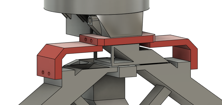
At this point I had every parts working together pretty well, including the electronics but I'll touch on that further down. But I had been working on this project on and off for quite some time, so much time in fact that the requirements changed. That's right, because of life circumstances we had to take in a family member's cat. The problem is, this machine was designed for two cats, not three…
No time to despair, we can do it, there must be a way to make it work for three cats. I figured I could just add another tunnel in the middle, and go back to a rotating "selector" to fill them one by one. I decided to with the an active method to split the food instead of a passive one because even with just two tunnels it had a tendency to fill one more than the other, because the dispenser rotates so the food doesn't fall equally on both sides. I didn't feel like printing a thousand prototypes to figure out exactly the geometry required to have a fair three-way split.
And who would have thought, it was actually not too hard to modify the design. It was just a matter of "extending" one of the tunnels past the split and cut it to create the "selector" and adding a third tunnel that matches with the position of said selector when it's rotated midway.
Then it's just a matter of attaching the tunnels to the rest of the machine, with the brace showed here in red. One of the reason the whole CAD file looks like Frankenstein's monster is because I designed the part one at a time, not always knowing what the next part would look like, so the later parts sometimes need to get a bit creative to fit with the previous ones without having to reprint everything.
The Electronics
With the hardware all taken care of let's take a look at how everything gets controlled. I have an Arduino Nano (or a clone of it anyways) to control the dispensing motor, the servo and read the sensors. To control the motor it uses a double-H bridge. There's a couple of resistance to read the photresistors. This board doesn't have much more on it, just bunch of connectors and a USB cable to connect to the ESP32. As always, I just mount everything on some perfboard and add wires until everything is connected as it should.
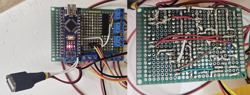
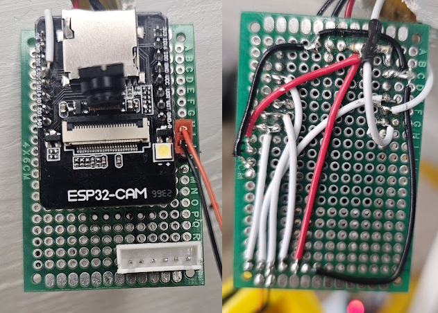
The ESP32 board isn't much more complex, it's just some headers for the chip, another USB connector and a JST header for programming the chip.
The JST connector was quite an improvement, before that every time I wanted to reprogram the ESP I had to press the BOOT button then press the reset button. It's not too annoying if you only have to do it once but when you to do it repeatedly and the board is in an inconvenient location it gets tiring real quick. Luckily I accidentally burned the programmer board that came with the ESP, I had to get a generic programmer and it was a perfect occasion to setup a good workflow where it automatically resets the board into programming mode when uploading code.
The Coding
On the Arduino side the code is pretty simple, it waits for commands on the serial port, execute them and outputs a response. For dispensing it rotates the motor and reads the encoder with a bunch of timers and debouncing to make sure it actually rotated correctly. There's a pin change interrupt to read the chute laser sensor. The three failure modes are if the motor gets stuck, if the laser fence is not triggered or if the laser path is broken before it starts rotating the motor, as that would mean food is stuck in the chute. After dispensing it outputs the results, either the error code or success, back to the serial.
There's a lot more business happening on the ESP32. Here's a little list of the things it handles.
- Monitoring the time and triggering dispensing events
- Communication with the Arduino
- Serving the Interface's webserver
- Handling communication on the WebSockets
- Streaming the camera
- Sending a Discord and Pushover notification after dispensing
The websocket's server is registered under a path that contains a password so you can't only see the camera that's streamed over WS or change the settings if you have the password. eg: ws://website.com/ws/PASSWORD_HERE
For Discord notification I use the webhook feature, super simple and easy. I also added Pushover notifications, which is an app you install on your phone and it gives you push notifications, the advantage is that the push notification could include an image at the time, it doesn't seem to work anymore so that part is a bit useless for me.
When the ESP32 boots up it tries to connect to the last wifi config. If it hasn't managed to connect after 30 seconds, it starts its own wifi access point, from which you can access the Interface and make it connect to one of the available wifis.
The Interface
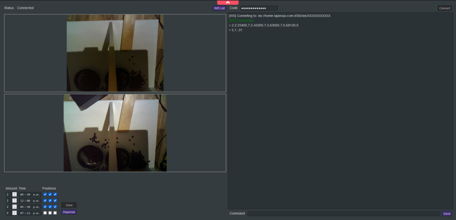
The Interface is a website in HTML, JS and SCSS. It gets built into minimized files using webpack, the hot-reload feature is also useful for development. There's one box for the last camera capture, one for the live camera stream, an area to set the actual dispensing settings, time and amount. There's also a button to get a list of available wifis and connect to one of them. The console logs all the commands that gets sent and received on the websocket and let you manually send commands. The field above the console is for putting the access password, without it nothing is accessible except the camera capture box. It uses JS localStorage to save the password so you don't need to enter it every time. I also made sure the website is responsive on mobile, as that's probably how I'll access it most of the time.
The Sharing
At this point there's basically three different programs that need to talk to each others, the Arduino, the ESP32 and the Interface. To help them understand each other I listed the shared constants and enums in a JSON file and made a JS script that I can execute using NodeJs (which I'm already using to build the Interface). The script generates a C++ header files with all the constants populates as well as a new JSON file with the new values. It then copies those files to each project's folder. Now each project can include either the header (for Arduino and ESP) or the JSON (for the Interface) so that they always use the same values for commands and share the same constants!
{
  "commands":
  {
    "ESP":
    [
      "Capture",
      "Dispense",
      "SetDispensingSetting",
      "SaveDispensingSettings",
      "WifiList",
      "WifiStatus",
      "WifiConnect",
      "Temperature"
    ],
    "ARD":
    [
      "Dispense",
      "Reservoir"
    ]
  },

  "enums":
  {
    "DispensingResult":
    [
      "Started",
      "Ok",
      "NoOutput",
      "PaddleStuck",
      "FoodJammed"
    ]
  },

  "constants":
  {
    "DispensingEventMax": 4,
    "PositionCount": 3
  }
}
The Heating
So everything is finally working, everything is perfect, now you just make a little cover for the ESP32 to protect it and hold the camera in place, what could go wrong?
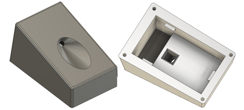
Somehow putting the cover on massively decrease performance, until the chip disconnect from wifi and is unreachable. Uh what's going on now…
Turns out the chip was overheating and it only started happening after I trapped it inside a thick-walled enclosure. I tried drilling a bunch of holes in the box but that didn't help. I then spent a considerable amount of time trying different power settings in the hope of reducing the heat dissipated but nothing help. I finally reluctantly resigned myself to putting a fan inside the case, I already had a fan of the right size but I wasn't too happy because I knew it would end up noisy. Still, I was out of options so I printed the new case with a spot for the fan and some holes for the exhaust. And… it worked! The chip was cooler than ever! Yet I was not satisfied, as predicted the fan made noise, and so I pushed a little bit farther, that's when it hit me! The problem was the camera! After measuring the current draw when I don't initialize the camera module at all I realized it was pulling more than have the total current for that board. After playing with the settings I managed to find how to turn it off when not in use. No more overheating even without the fan, yay!
The Wifi
So everything is finally working, everything is perfect, now you just have to close up the machine and put it in its final place, what could go wrong?
It seems like everything is working but the web interface is extremely slow and most of the time it can't connect at all. Uh what's going on now… Bring the machine back down the stairs, disassemble, debug, find the problem, all over again. This project sure is starting to take a long time, started it what.. hmm.. let me count, 2 years ago?? Alright time to wrap this thing up.
For some reason it seems the ESP's wifi connection is really weak, even when really close to the router. What makes it even stranger is that the connetion is bad even with an external camera. Trying with a different ESP32-CAM module gave the same result. Then I realized that the wifi performance was much better when it wasn't on the machine's perfboard. Which is strange since there's almost nothing on that board. After trying all kind of things including dubious methods of shielding, I finally realized that the issue was the UART RX pin coming from the Arduino's TX. That pin was giving 5V, I never had issue with directly connecting 5V to the esp32 even though it's supposed to be used with 3.3V but I guess it was messing with RF for the wifi one way or another. That took me a long time to find, but in the end a simple voltage divider solved the problem.
The Finishing Touches
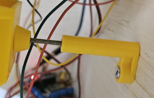
The tunnel was drooping lower than it should have been, and that was a problem as they were designed to end just above the low profile stainless bowls I got especially for this project. I should have expected that with all the different 3D printed parts, the flex adds up. After probing a pushing from different places I established that holding it from the back would be the most ideal solution. I quickly designed a little piston, a 3D printed tube with a heat-set insert at the end, a long screw and a cap for that screw that also has a heat-set insert. heat-set insert are awesome and I always forget they are a great option.
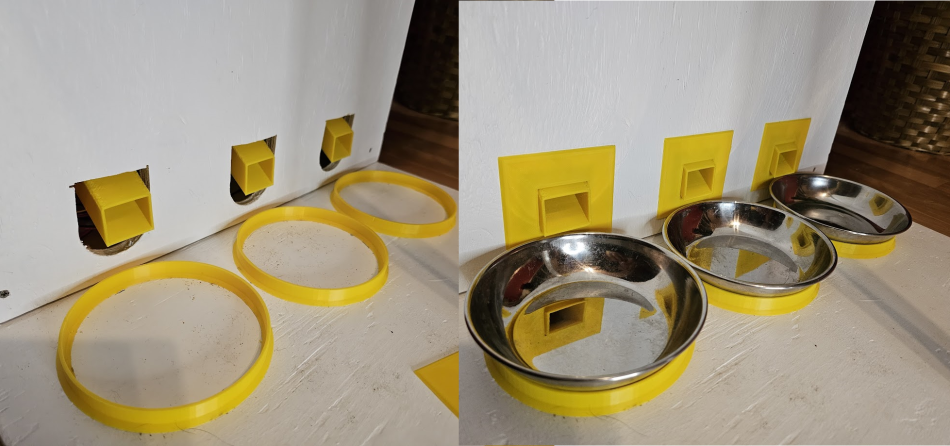
Next was covers to put around the tunnels where they come out of the wall. There was no way I was going to cut nice holes of the perfect shape and dimension in the middle of the wood board so I intentionally oversized them and printed covers to hide it.
The last thing was realizing my cats are very aggressive eater and like to push bowls around when they eat. At firs I thought of putting magnets under them but the bowls are barely magnetic so I would have to glue one set of magnets to the bowls and one to the floor of the machine, a bit cumbersome. Plus magnets near food is stressful since they can be quite a hazard when ingested. I was thinking about crazy solutions like gluing a nut to the bowl and screwing from the bottom when I remember I hold the holy power of 3d printing and can simply print little holders:
The Result
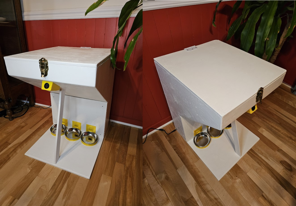
After many a trouble and literally years of efforts, I finally made it, the automatic cat feeder machine! It works perfectly, the cats now leave me alone in the morning and it does everything as it was supposed to. In retrospect, I could have made it smaller, especially since we don't even have the cat litter furniture that was supposed to be its companion. I'm very happy with the result, and also very happy it's done!
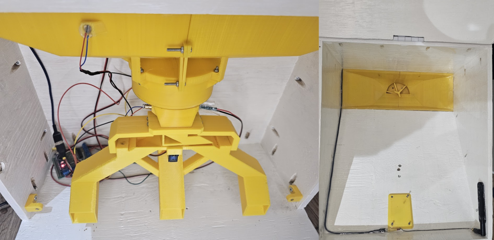
Here's come pictures of the inside
And of the outside
I had a lot of fun with this project, this is exactly the kind of stuff I enjoy making, as always I learned a lot and that's at least half the pleasure. I made this blog post as a way of reflecting on the adventure and sharing the fun. I'm not sure if there's much to gain for other people here but if you're still reading I imagine you got something out of it! Thank you for reading and see you on the next one!